EMI DC Motor Filtering Basics
Summary
Traditionally the automotive industry only required filtering for the AM and FM bands (150 KHz – 200 MHz) because electromagnetic interference at car radios frequencies were the main concern. As more sophisticated electronics are introduced in automobiles today (Bluetooth applications, digital radio, GPS, etc.), EMC (Electromagnetic Compatibility) requirements are being expanded out to 3 GHz in most instances.
EMI components, when properly implemented, can provide the needed broadband filtering to meet these new requirements. A single EMI component provides superior filtering performance over other passive filter solutions, some comprised of as many as seven components in DC motors. EMI components come in standard capacitor sizes, 0603, 0805, 1206, 1210, 1410, and 1812; and can be made from different materials (ceramic, MOV, and ferrite) for varying applications. An EMI component in ceramic material is recommended used for DC motor applications. Ceramic offers the broadest filtering range with the best performance.
This application note outlines the four main design principles of DC motor design that maximize EMI performance in order to comply with the EMC requirements set forth by the automotive industry. The goal is to provide design engineers with the ideal EMI component implementation and a general knowledge of basic EMC principles for DC motor designs. Topics covered in this application note will include:
- Principle #1 – Understanding EMI Components.
- Principle #2 – The Motor Housing
- Principle #3 – Implementing EMI Components
- Principle #4 – Dual Ground Connection throughout Motor
- Bringing It All Together
Although this application note is tailored for DC motor design, these principles can be applied to any design that requires broadband filtering.
Principle #1
Principle #1 – Understanding EMI Components. To apply EMI components in a design, it is important to have a general understanding of what EMI Technology is and how to apply it.
- EMI is a four terminal device. The terminals are identified as A, B, G1 and G2 (left Figure 1). A and B are connected across the power leads and G1 and G2 are attached to ground (right Figure 1). (For DC motors, ground would be the motor housing.)
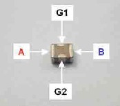
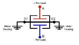
Figure 1. EMI made of ceramic (left). EMI schematic symbol (right). - EMI is connected in a circuit as a bypass component. This is important because it doesn’t limit DC current and has no effect on torque performance. Because the chip has side terminations, it is often confused for a feedthrough capacitor or several standard capacitors in one structure or inductors with an X-cap.br />

EMI is a bypass component that is NOT comprised of standard passive components - Although an internal electrode layer commonly attaches the G1 and G2 terminations within the device, it is important that both terminations are connected to an external ground structure. (Grounding will be discussed in more detail in Principle #4.)
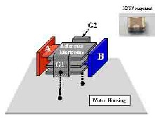
Figure 3. Both terminals, G1/G2, should be in parallel to the motor housing. - EMI components reduce EMI internal to the device by means of field cancellation. By contrast, standard components use “brute force” by using capacitance to shunt noise or inductors to block noise with high impedance.
- A practical rule-of-thumb for choosing the correct part size and the amount of capacitance for a DC motor with an operating voltage of 12 -24 volts is to start with a 50 volt 1410 EMI component with approximately 400 nf of capacitance.
Principle #2
Principle #2 – The Motor Housing. To design the DC motor housing with EMC in mind, there are several aspects must be considered.
- The material make up of the motor housing is critical to reducing EMC emissions. The material should be made of metal or metalized to contain radiated waves (Left Figure 4). The relative permeability of the metal should be considered. The metal should reflect or absorb the incidental waves created by the aperture (Right Figure 4).
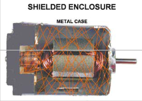
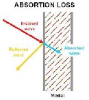
Figure 4. Radiated noise contained by the motor housing (left). The shield, or housing, should reflect or absorb radiated noise. Picture courtesy of Jastech EMC Consulting, LLC. - The material make up for the end cap or end cover should also be metal or metalized. Plastic covers by themselves have no shielding property and allow radiated waves to exit the housing (Figure 5). (NOTE: If plastic covers are used, the brushes MUST be contained within the dimensions of the metal housing, NOT within the dimension of the plastic end cap or cover. No exception can be made, EMC requirements CANNOT be met!)
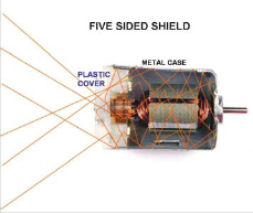
Figure 5. Plastic end caps do not contain radiated noise in the housing. Picture courtesy of Jastech EMC Consulting, LLC. - Vent holes in the motor housing are the next concern. Linear dimension NOT the area of the opening is what is key. Figure 6 (left) shows the induced current flow of a shield (housing). Although the area of the rectangle is the same as 4 circles added together, the 4 circles disrupt current flow less. The interruption of current can cause the slot to become an antenna and radiate noise. Vent holes should also be located as far away from the brushes as possible, because the brushes are the biggest “noise makers” (right Figure 6).
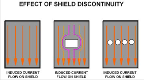
Figure 6. Vent holes in the motor housing can disrupt induced current flow (left). Vent holes should be located away from the brushes (right). Picture courtesy of Jastech EMC Consulting, LLC. - Seams and joints in the motor housing or the connection between the motor housing and end cover can also be a source of radiated emissions. The connection should have some form of interlocking or overlapping joint and/or lip. The angles created by the joints/lip make it difficult for radiated waves to penetrate outside of the housing. In addition, the joints/lips increase contact surface area, therefore improving skin current flow. To ensure good conductivity, any oil and paint must be removed from the joints or seams. Figure 7 depicts some examples of proper seams and joints.
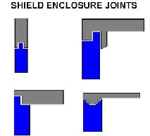
Figure 7. Proper joints and seams reduce the amount of radiated noise that can escape the motor housing. Picture courtesy of Jastech EMC Consulting, LLC. - The power leads should exit the motor housing in close proximity to each other. Figure 8 demonstrates proper and improper lead exit points in the motor housing. This serves three purposes.
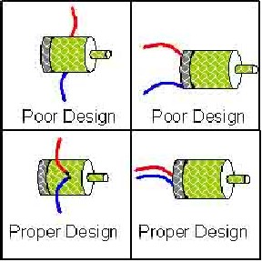
Figure 8. Power leads should exit the motor housing in close proximity.- From an EMC point of view, the closer the leads are to each other, the smaller the loop area is between the leads and the more mutual inductance or cancellation of noise occurs (Figure 9).
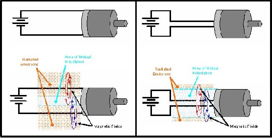
Figure 9. Mutual inductance cancels noise. To maximize mutual inductance, loop area of the power leads should be minimized. - EMI can further reduce loop area when properly attached due to the internal structure (Figure 10). To guarantee maximum performance, inductance from the A/B terminal should be minimized, which means reducing the distance from the A/B terminal and the leads.
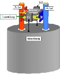
Figure 10. EMI further reduces loop area because the plates are only a dielectric apart. The result is maximum mutual inductance.
- From an EMC point of view, the closer the leads are to each other, the smaller the loop area is between the leads and the more mutual inductance or cancellation of noise occurs (Figure 9).
- Crimping tabs that extend from the inside surface of the motor housing and contact the outer surface can couple interior housing noise to the outside thereby bypassing the filter (Figure 11).
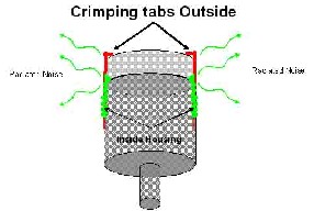
Figure 11. Crimping tabs that come from inside the motor housing to the outside can be a source of radiated noise. Picture courtesy of Jastech EMC Consulting, LLC. - For motors that have a shaft that extends into an assembly, the shaft can become an antenna that radiates noise as shown with the crimping tabs. To reduce radiated noise, ensure that metal bearings or bushings are properly grounded to the housing (Figure 12).
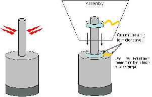
Figure 12. Bearing and bushings should be properly grounded if a shaft extends into an assembly.- Consideration should also be given to the choice between bearing and bushings.
- Bushings should be made of solid metal that is conductive and impregnated with oil for lubrication. The shaft fits inside the bushing and makes continuous contact (Figure 13). Therefore if the bushing is properly grounded, a ushing would be the ideal choice from an EMC point of view.
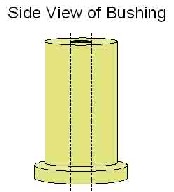
Figure 13. A bushing is the ideal choice because of the area surface contact with the shaft. - Bearings have less surface area contact than bushings. If bearings are used, conductive grease will help in providing a good ground. In addition, a conductive metal cover that makes good contact with the inner and the outer rings will also help.
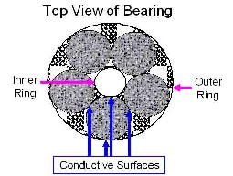
Figure 14. A bearing can be used if proper considerations are given.
- Bushings should be made of solid metal that is conductive and impregnated with oil for lubrication. The shaft fits inside the bushing and makes continuous contact (Figure 13). Therefore if the bushing is properly grounded, a ushing would be the ideal choice from an EMC point of view.
- Consideration should also be given to the choice between bearing and bushings.
Principle #3
Principle #3 – Implementing EMI Components. The way EMI components are attached and placed can have major effects on how well they perform. In this section, the proper attachment and placement of EMI components is discussed. The following are the key points for maximum broadband filtering performance:
- Start by remove all filtering components that are currently used. EMI components internally cancel noise due to the unique structure. Through experience and testing, some filtering devices have been found to interfere with the internal canceling effect, and degrade overall EMC emissions.
- The best way to attach EMI components is to use a brush card or small PCB (Printed Circuit Board). One or two layer PCBs can be used. Considerations for using a PCB are: (Note: The following examples use a one layer PCB)
- Both G1 and G2 terminations on EMI should be soldered to a solid trace (Figure 15). By soldering both terminals to the trace, a parallel connection now exists from the component to the trace. (A more comprehensive discussion of this is described in Principle #4.)
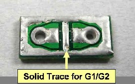
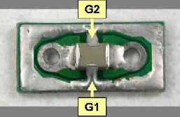
Figure 15. Both terminals, G1/G2, should be attached in parallel with a solid trace. - Traces on the brush card or PCB should be short and wide to minimize inductance (Figure 16). Parasitic inductance can impair a component’s performance.
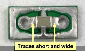
Figure 16. Traces to the EMI component should be short and wide to reduce inductance. - Power leads should be connected to EMI “thru” the brush card or PCB to prevent noise from bypassing the component (Figure 17). When the power leads are attached “thru” the PCB and the PCB is attach to the motor housing as in Figure 18, the noise energy is forced into the EMI component.
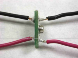
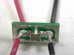
Figure 17. Power leads should go “thru” PCB.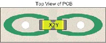
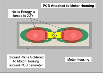
Figure 18. When power leads are attached “thru” the PCB, noise energy is forced to the EMI component. - The EMI component and PCB/Brush card should be coated with a conformal coat or nonconductive coating to prevent metal dust from the brushes from forming a conductive coating that can become conductive. A conductive coating of metal dust can short the part causing thermal failure. (For prototyping, clear nail polish is an easy inexpensive nonconductive coating.)
- The brush card or PCB should be located at the inside or just outside of the housing/end cap where the power leads exit. This placement ensures that the EMI component will be the last place the noise will pass before or just after leaving the motor housing (Figure 19).
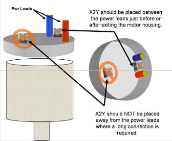
The placement location of EMI components is more important than that of standard capacitors. EMI internally cancels noise whereas standard capacitors use capacitance to shunt noise to ground. All the radiated and conducted noise must be focused into the part to ensure maximum cancellation occurs.
- Both G1 and G2 terminations on EMI should be soldered to a solid trace (Figure 15). By soldering both terminals to the trace, a parallel connection now exists from the component to the trace. (A more comprehensive discussion of this is described in Principle #4.)
Principle #4
Principle #4 – Dual Ground Connection throughout Motor. This concept is probably the easiest one to understand, but the most neglected of all. Dual or multipoint grounding is when more than one connection to ground is made (left Figure 20). The benefit of having multiple contacts to ground is that the connections are in parallel.
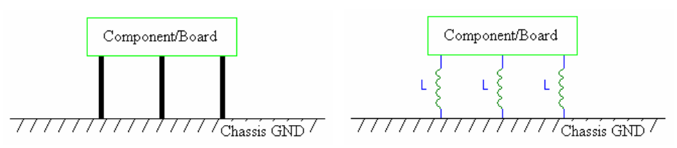
Figure 20. Multiple or parallel connections to ground reduce the total impedance between the component and ground.
For example, assume that all the connections to ground have an equal inductance, L. A parallel configuration reduces the total inductance between the component and ground by a ratio of 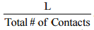 . The total inductance between the component and ground in Figure 20 is L/3 or reduced by one-third.
Internal to the EMI device is a multiple layer parallel ground structure, which is connected to the G1 and G2 terminals. This structure is only as good as the external G1 and G2 connections. If both G1 and G2 are attached to a solid trace as previously discussed, a parallel connection exists between the EMI component and the trace. Once again, the reference ground of the trace ground is only as good as its connection to the ground plane of the brush card or PCB. Dual connections, whether by vias or some other means, would be appropriate between the trace and the ground plane. The same holds true for the connection of the ground plane to the motor housing and the motor housing to any further reference ground point.
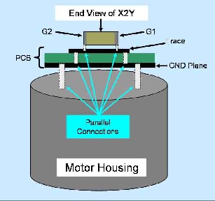
Figure 21. Ground connection hierarchy for an EMI component. Note: The above hierarchy uses a 2 layer PCB. A single layer PCB may also be used as illustrated in the Principle #3 example.
Although not every structure described in Figure 21 is needed or exists for all motor applications, the idea that dual or multiple connections throughout the ground hierarchy is the same. Each level of the ground hierarchy is dependent on the connection inductance of the previous level.
A key difference EMI components have over standard passive components is that EMI cancels noise rather than blocking or shunting it. When shunting the oise a chassis ground is required from the motor housing. With EMI the motor housing can be left “floating”.
The material used for grounding is also important. Many times copper braid is used in the grounding hierarchy. When copper corrodes it loses its conductivity. A motor that passes emissions can fail a few days later because of corrosion. Copper braid should be tinned to prevent corrosion.
Bringing It All Together
Brining It All Together. To illustrate several of the concepts outlined in this application note, a prototyping example is provided in this section. Note that for this example a small motor is used, but EMI will also work on larger motors because it is a bypass component and does not affect DC current.
- Figure 22 is a DC motor. The power leads are far apart and the end cap is plastic.
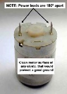
Figure 22. DC motor used to illustrate prototyping example. Picture courtesy of Jastech EMC Consulting, LLC. - A small PCB is attached and the motor leads are brought together underneath the PCB and are then brought through the PCB close together so that the EMI component can be soldered between power leads.
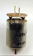
Figure 23. PCB with an EMI component is attached. Picture courtesy of Jastech EMC Consulting, LLC. - Conductive tape has now been wrapped around the motor housing and over the edge and onto the top ground area of the small PCB. This works to contain radiated noise and will focus the noise to the exit leads and EMI.
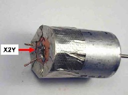
Figure 24. Metal tape is used to enclose the end of the housing. Picture courtesy of Jastech EMC Consulting, LLC. - For prototyping, metal tape is soldered to the motor housing for lowest impedance ground connection. Soldering the tape in multiple areas will improve the ground impedance.
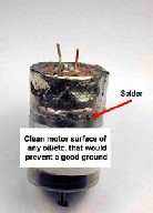
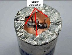
Figure 25. Adding solder connections around the edge of the tape ensures emissions are contained. Picture courtesy of Jastech EMC Consulting, LLC.
Figure 26 and Figure 27 show the radiated and conducted emissions before and after the motor was prototyped.
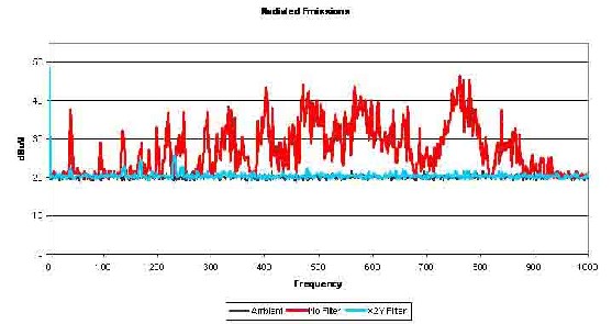
Figure 26. Radiated test results of prototyped motor. Data courtesy of Jastech EMC Consulting, LLC.
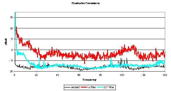
Figure 27. Conducted test results of prototyped motor. Data courtesy of Jastech EMC Consulting, LLC.
If the radiated emissions are still not meeting requirements, check or try the following:
- Check to see if Principles #2-4 have been met. If these principles have not been met, EMI or any other passive filter will most likely NOT meet EMC requirements due to design issues.
- If Principles #2-4 HAVE been met, then try
- An EMI component with more capacitance. More capacitance can help reduce emissions at the low end of the spectrum.
- A different size EMI component. Different geometries and aspect ratios have different cancellation characteristics.
This methodology is a good starting point for engineers as they gain experience using EMI components. A quick design reference is shown in Figure 28.
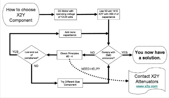
Figure 28. Design flow chart. Note that once a solution is found, other EMI components sizes should be tried to find the most cost effective solution to meet EMC requirements
Conclusion
Many EMC compliance issues can be solved or met by properly applying the principles discussed in this application note during the design process. Dealing with EMC compliance issues after the design process can delay production and be very costly to fix.
This application note outlined the ideal design implementation of EMI and design solutions for meeting EMC requirements. Exceptions to these principles do exist, and in some cases an ideal design is neither practical nor needed for compliance.
Other application notes on DC motors and EMC solutions can be found at www.x2Y.com.