High Temperature Stacked Capacitors
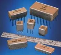
Formerly known as "SMPS T-Series"
Key Features:
- Rated Voltage: 50VDC to 200VDC
- Dielectrics Type: NP0, X7R
- Capacitance Range: .01 μF - 47 μF
- For Use at Temperatures Up to 200°C
- Rated Working Voltages from 50V to 2KV
- Rugged Stack with Hi-Temp Lead-Attachment
- MLC Designs Utilizing Military Grade Ceramics
- Custom Sizes, Values, and Voltages Available
Applications:
- Oil Well Logging (Downhole)
- Geophysical Probes
- Jet Engine Controls
| Size Code / EIA Size | NP0 Max Capacitance (μF) | X7R Max Capacitance (μF) | ||||
|---|---|---|---|---|---|---|
| 50V | 100V | 200V | 50V | 100V | 200V | |
| EM / 2324 | 0.56 | .0.47 | 0.22 | 1.20 | 0.68 | 0.33 |
| 0.10 | 0.82 | 0.39 | 2.20 | 1.20 | 0.68 | |
| 0.15 | 0.12 | 0.68 | 3.30 | 1.80 | 1.00 | |
| 0.22 | 0.18 | 0.82 | 4.70 | 2.70 | 1.20 | |
| 0.27 | 0.22 | 0.10 | 5.60 | 3.30 | 1.50 | |
| FP / 3839 | 0.12 | 0.10 | 0.10 | 2.70 | 1.50 | 0.82 |
| 0.22 | 0.18 | 0.18 | 4.70 | 2.70 | 1.50 | |
| 0.33 | 0.27 | 0.27 | 8.20 | 3.90 | 2.20 | |
| 0.47 | 0.39 | 0.39 | 12.0 | 5.60 | 3.30 | |
| 0.56 | 0.56 | 0.56 | 15.0 | 8.20 | 3.90 | |
| NF / 43102 | 0.47 | 0.39 | 0.22 | 10.0 | 5.60 | 2.70 |
| 0.82 | 0.68 | 0.39 | 18.0 | 10.0 | 4.70 | |
| 1.20 | 1.00 | 0.68 | 27.0 | 15.0 | 8.20 | |
| 1.80 | 1.50 | 0.82 | 39.0 | 22.0 | 10.0 | |
| 2.20 | 1.80 | 1.00 | 47.0 | 27.0 | 12.0 | |
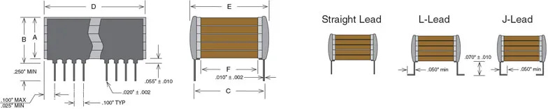
| Case Size | A | B | C | D | D | E | F | Leads per side |
|---|---|---|---|---|---|---|---|---|
| (max") | (max") | ±0.25 | (min") | (max") | (max") | (min") | ||
| T05 | .120 | .185 | .250 | .224 | .275 | .300 | .080 | 3 |
| T25 | .240 | .305 | ||||||
| T35 | .360 | .425 | ||||||
| T45 | .480 | .545 | ||||||
| T55 | .650 | .715 | ||||||
| T04 | .120 | .185 | .400 | .350 | .425 | .440 | .180 | 4 |
| T24 | .240 | .305 | ||||||
| T34 | .360 | .425 | ||||||
| T44 | .480 | .545 | ||||||
| T54 | .650 | .715 | ||||||
| T03 | .120 | .185 | .450 | .950 | 1.075 | .500 | .180 | 10 |
| T23 | .240 | .305 | ||||||
| T33 | .360 | .425 | ||||||
| T43 | .480 | .545 | ||||||
| T53 | .650 | .715 |
| NP0 Dielectric | X7R Dielectric | |
|---|---|---|
| Temperature Coefficient: | 0 ± 30ppm/°C, -55 to 125°C | 0 ±15% (-55 to 125°C) |
| Cap Drop at 200°C: | minus 0.5% max | minus 45% max |
| Dissipation Factor: | .001 (0.1%)max, 1Khz, 25°C | .025 (2.5%)max, 1Khz, 25°C |
| Insulation Resistance: @ 25°C | 1000 Ohm-Farads or 100 Gigohms whichever is less @ 25°C, WVDC | 1000 Ohm-Farads or 100 Gigohms whichever is less @ 25°C, WVDC |
| Insulation Resistance: @ 200°C | 1 Ohm-Farads or 100 Megaohms whichever is less @ 200°C, WVDC | 1 Ohm-Farads or 100 Megaohms whichever is less @ 200°C, WVDC |
| Dielectric Strength: | 2.5 X WVDC, 25°C, 50 mA max. | 2.5 X WVDC, 25°C, 50 mA max. |
| Test Parameters: | 1Khz ± 50Hz, 1.0±0.2 VRMS, 25°C | 1Khz ± 50Hz, 1.0±0.2 VRMS, 25°C |
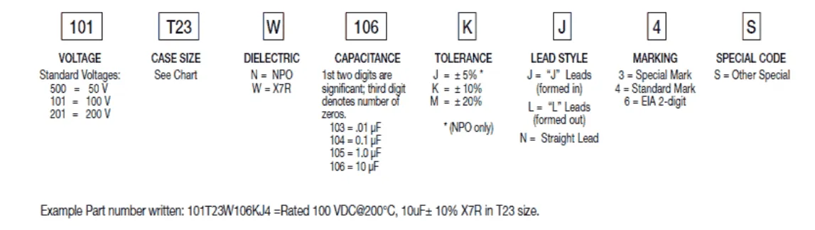
How to Order
Valid options are shown except for Capacitance
A typical PN is R2NF101W106K2J1001W. This part number breaks down as follows:
Capacitors SMPS T-Series BME - 2 chips, 43102, X7R, 100V, 10μF±10%, "J" Leads, Waffle Pack
New Johanson Global Part Number Breakdown
* Not all combinations create valid part numbers, ask our Apps Engineering Team for assistance creating a valid part number Request for assistanceClick below to see the new Global Part Number Reference Chart for this product
The legacy info below is for reference only.
Johanson has instituted a new Global Part Numbering (GPN) system.
Only the part number is changing. The parts are produced with the exact same materials, manufacturing processes, manufacturing controls, dimensions, physical attributes and testing as the parts supplied with the legacy part numbers.
The GPNs will be phased in over the next several years and are planned to be completed by January 1, 2026.
We will continue to quote and accept orders with the current (legacy) part numbers throughout this period.
Beginning January 1, 2022, all samples will be provided with the GPN.
Updates associated with this change will occur periodically.
A database for the approximate 2 million crosses can be accessed at: https://www.johansontechnology.com/pn-search