Mini-Switchmode® Capacitors
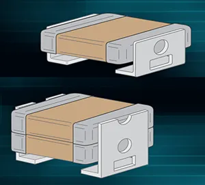
Mini-Switchmode® Capacitors for DC-DC Power Circuits in High-Stress Environments
Key Features:
- Enhanced Stress Relief: Reduces risk of cracking caused by thermal cycling, TCE mismatches, and board flexing.
- Wide Voltage Range: Available in 25V to 500V DC ratings to suit diverse power applications.
- Customizable Options: Custom sizes, voltages, and capacitance values available for specialized designs.
- Optimized for Power Applications: Suited for DC-DC power supply circuits, ensuring stable and reliable performance.
General Specifications:
- Crack-Resistant Design: Built to withstand thermal cycling, TCE mismatches, and mechanical stress.
- Voltage Ratings: 25V to 500V DC, catering to various electronic power systems.
- Custom Engineering Available: Tailored solutions for unique electrical and mechanical requirements.
- Power Supply Compatibility: Designed for DC-DC converter applications in demanding environments.
| Size Code | EIA Chip Size | # of Stacks | NP0 Max Capacitance (μF) | X7R Max Capacitance (μF) | ||||||||
|---|---|---|---|---|---|---|---|---|---|---|---|---|
| 25V | 25V | 50V | 100V | 200V | 500V | 25V | 50V | 100V | 200V | 500V | ||
| DV | 1825 | 1 | 0.056 | 0.047 | 0.039 | 0.027 | 0.018 | 1.5 | 1.2 | 0.75 | 0.56 | 0.27 |
| DV | 1825 | 2 | 0.11 | 0.094 | 0.078 | 0.054 | 0.036 | 3.0 | 2.4 | 1.5 | 1.1 | 0.54 |
| DV | 1825 | 3 | 0.16 | 0.14 | 0.11 | 0.081 | 0.054 | 4.5 | 3.6 | 2.2 | 1.6 | 0.81 |
| DV | 1825 | 4 | 0.22 | 0.18 | 0.15 | 0.10 | 0.007 | 6.0 | 4.8 | 3.0 | 2.2 | 1.0 |
| EH | 2225 | 1 | 0.068 | 0.056 | 0.047 | 0.033 | 0.027 | 2.7 | 2.2 | 1.5 | 1.2 | 0.39 |
| EH | 2225 | 2 | 0.13 | 0.11 | 0.094 | 0.066 | 0.054 | 5.4 | 4.4 | 3.0 | 2.4 | 0.78 |
| EH | 2225 | 3 | 0.20 | 0.16 | 0.14 | 0.010 | 0.081 | 8.1 | 6.6 | 4.5 | 3.6 | 1.1 |
| EH | 2225 | 4 | 0.27 | 0.22 | 0.18 | 0.13 | 0.10 | 10 | 8.8 | 6.0 | 4.8 | 1.5 |
| Dimensions Applicable to specific sizes: | 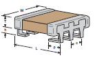 | 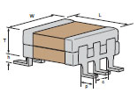 | 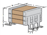 | 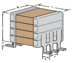 |
||||||||||||||
| in. | mm | |||||||||||||||||
| h ± .010 | .070 | 1.78 | ||||||||||||||||
| c Typ. | .100 | 2.54 | ||||||||||||||||
| p ± .015 | .065 | 1.65 | ||||||||||||||||
| Dimensions Applicable to specific sizes: | DV / EIA 1825 | EH / EIA 2225 | EH / EIA 2225 | DV / EIA 1825 | EH / EIA 2225 | DV / EIA 1825 | EH / EIA 2225 | DV / EIA 1825 | ||||||||||
| in. | mm | in. | mm | in. | mm | in. | mm | in. | mm | in. | mm | in. | mm | in. | mm | |||
| L max | .280 | 7.11 | 0.24 | 6.1 | 0.28 | 7.11 | 0.24 | 6.1 | 0.28 | 7.11 | 0.24 | 6.1 | 0.28 | 7.11 | 0.24 | 6.1 | ||
| W max | .270 | 6.86 | 0.27 | 6.86 | 0.27 | 6.86 | 0.27 | 6.86 | 0.27 | 6.86 | 0.27 | 6.86 | 0.27 | 6.86 | 0.27 | 6.86 | ||
| T max | 0.95 | 2.41 | 0.095 | 2.41 | 0.19 | 4.83 | 0.19 | 4.83 | 0.285 | 7.24 | 0.285 | 7.24 | 0.38 | 9.65 | 0.38 | 9.65 | ||
| Note: J-Lead and L-Lead options are available on all sizes above | ||||||||||||||||||
| X7R | NP0 | ||
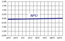
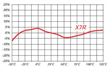
| TEMPERATURE COEFFICIENT: | -55 to 125° | 0 ± 15% | 0 ± 30ppm/°C |
| DISSIPATION FACTOR: | 1kHz, 25°C | 2.5% max | 0.1% max |
| AGING RATE: | % per decade hour | 2.5% | none |
| INSULATION RESISTANCE: | 1000⟨F or 100G⟨, whichever is less at rated WVDC, 25°C | ||
| DIELECTRIC STRENGTH: | For 500V Ratings 750VDC, 25°C, 50mA max For 200V Ratings 2xWVDC, 25°C, 50mA max For 25-100V Ratings 2.5xWVDC, 25°C, 50mA max |
||
| CAP & D.F. MEASUREMENTS: | 1kHz ±50Hz; 1.0±0.2 VRMS, 25°C | ||
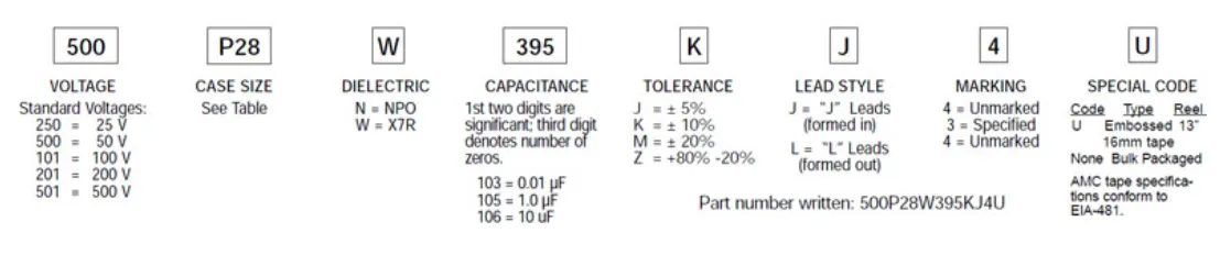
How to Order
Valid options are shown except for Capacitance
A typical PN is M2EH500W3995K1J1001U. This part number breaks down as follows:
New Johanson Global Part Number Breakdown
* Not all combinations create valid part numbers, ask our Apps Engineering Team for assistance creating a valid part number Request for assistanceClick below to see the new Global Part Number Reference Chart for this product
The legacy info below is for reference only.
Johanson has instituted a new Global Part Numbering (GPN) system.
Only the part number is changing. The parts are produced with the exact same materials, manufacturing processes, manufacturing controls, dimensions, physical attributes and testing as the parts supplied with the legacy part numbers.
The GPNs will be phased in over the next several years and are planned to be completed by January 1, 2026.
We will continue to quote and accept orders with the current (legacy) part numbers throughout this period.
Beginning January 1, 2022, all samples will be provided with the GPN.
Updates associated with this change will occur periodically.
A database for the approximate 2 million crosses can be accessed at: https://www.johansontechnology.com/pn-search