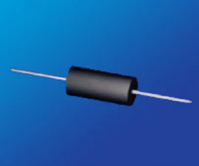
Resistor Wirewound High Power Rating

This specific product line is not for new designs.
Our Wirewound High Power Rating Resistors or RWH series have high power rating of up to 15 watts, and these resistors contains silicone coating that provides protection against high temperatures. These axial leaded resistors also feature excellent pulse handling, a temperature coefficient of as low as ± 20ppm/°C, and a complete welded construction. Additionally, the RWH series are capable of sustaining extreme voltage fluctuations making them well suited for industrial applications such as motor control, and medical applications such as MRI’s.
Miniature Axial

| Package Code | E01 | E02 | E03 | E04 | E05 | E06 | E07 | E08 | E09 | E10 | E11 | E12 | E13 | |
|---|---|---|---|---|---|---|---|---|---|---|---|---|---|---|
| Max Resistance (Ω) 1 | 3.4k | 3.4k | 7.5k | 7.5k | 10k | 10k | 12.5k | 25k | 32k | 50k | 95k | 150k | 260k | |
| Max Working Voltage (V) | 33 | 33 | 42 | 42 | 80 | 80 | 135 | 162 | 194 | 258 | 425 | 607 | 1050 | |
| Power Rating (W) | 1 | 1 | 1.5 | 1.5 | 2 | 2 | 3 | 4 | 5 | 6 | 7 | 10 | 15 | |
Dimensions Inches [mm] |
A ±0.062” [±1.57mm] |
0.250 [6.35] |
0.250 [6.35] |
0.312 [7.92] |
0.312 [7.92] |
0.406 [10.31] |
0.406 [10.31] |
0.350 [8.89] |
0.560 [14.22] |
0.500 [12.70] |
0.625 [15.88] |
0.875 [22.23] |
1.220 [30.99] |
1.780 [45.21] |
| B ±0.031” [±0.79mm] |
0.085 [2.16] |
0.085 [2.16] |
0.078 [1.98] |
0.078 [1.98] |
0.094 [2.39] |
0.094 [2.39] |
0.156 [3.96] |
0.187 [4.75] |
0.218 [5.54] |
0.250 [6.35] |
0.312 [7.92] |
0.312 [7.92] |
0.375 [9.53] |
|
| C 2 ±0.002” [±0.05mm] |
0.020 [0.51] |
0.025 [0.64] |
0.020 [0.51] |
0.025 [0.64] |
0.025 [0.64] |
0.020 [0.51] |
0.032 [0.81] |
0.032 [0.81] |
0.040 [1.02] |
0.040 [1.02] |
0.040 [1.02] |
0.040 [1.02] |
0.040 [1.02] |
|
MIL-R-26 / MIL-R-39007 |
RW-81 RWR-81 |
RW-81 RWR-81 |
RWR-82 |
RWR-82 |
RW-80 RWR-80 |
RW-80 RWR-80 |
RW-84 |
|||||||

1
For non-inductive windings / divide maximum resistance by 2
2
Lead Diameter: 18 AWG = 0.040" / 20 AWG = 0.032” / 22 AWG = 0.025" / 24 AWG = 0.020"
Axial

| Package Code | F01 | F02 | F03 | F04 | F05 | F06 | F07 | F08 | F09 | F10 | F11 | |
|---|---|---|---|---|---|---|---|---|---|---|---|---|
| Max Resistance (Ω) 1 | 500 | 2.5k | 2.5k | 7.5k | 7.5k | 10k | 10k | 12.5k | 22k | 22k | 40k | |
| Max Working Voltage (V) | 8.5 | 20 | 20 | 29 | 29 | 52 | 52 | 60 | 130 | 140 | 140 | |
Power Rating (W) |
U | 0.1 | 0.4 | 0.4 | 0.75 | 0.75 | 1.0 | 1.0 | 1.5 | 2.5 | 3.0 | 3.0 |
| V | 0.25 | 0.5 | 0.5 | 0.9 | 0.9 | 1.5 | 1.5 | 2.0 | 3.0 | 3.75 | 4.0 | |
Dimensions Inches [mm] |
A ±0.062” [±1.57mm] |
0.150 [3.81] |
0.250 [6.35] |
0.250 [6.35] |
0.330 [8.38] |
0.330 [8.38] |
0.406 [10.31] |
0.406 [10.31] |
0.350 [8.89] |
0.500 [12.70] |
0.560 [14.22] |
0.500 [12.70] |
| B ±0.031” [±0.79mm] |
0.094 [2.39] |
0.085 [2.16] |
0.094 [2.39] |
0.094 [2.39] |
0.094 [2.39] |
0.094 [2.39] |
0.094 [2.39] |
0.156 [3.96] |
0.187 [4.75] |
0.187 [4.75] |
0.250 [6.35] |
|
| C 2 ±0.002” [±0.05mm] |
0.018 [0.45] |
0.020 [0.51] |
0.025 [0.64] |
0.020 [0.51] |
0.025 [0.64] |
0.020 [0.51] |
0.025 [0.64] |
0.032 [0.81] |
0.032 [0.81] |
0.032 [0.81] |
0.040 [1.02] |
|
| MIL-R-26 / MIL-R-39007 | RW-70 | RW-70 | RW-69 | RW-79 | ||||||||
| Package Code | F12 | F13 | F14 | F15 | F16 | F17 | F18 | F19 | F20 | F21 | F22 | F23 | |
|---|---|---|---|---|---|---|---|---|---|---|---|---|---|
| Max Resistance (Ω) 1 | 40k | 30k | 45k | 45k | 91k | 65k | 95k | 150k | 100k | 154k | 260k | 320k | |
| Max Working Voltage (V) | 140 | 140 | 210 | 210 | 360 | 390 | 504 | 650 | 590 | 620 | 850 | 1500 | |
Power Rating (W) |
U | 3.0 | 3.0 | 4.0 | 4.0 | 5.0 | 5.0 | 5.0 | 7.0 | 7.0 | 7.0 | 10 | 15 |
| V | 4.0 | 3.5 | 5.5 | 5.5 | 6.5 | 6.5 | 6.5 | 9.0 | 9.0 | 9.0 | 13 | - | |
Dimensions Inches [mm] |
A ±0.062” [±1.57mm] |
0.500 [12.70] |
0.500 [12.70] |
0.675 [17.15] |
0.675 [17.15] |
0.875 [22.23] |
0.970 [24.64] |
1.025 [26.04] |
1.375 [34.93] |
1.400 [35.56] |
1.200 [30.99] |
1.780 [45.21] |
1.810 [45.95] |
| B ±0.031” [±0.79mm] |
0.250 [6.35] |
0.200 [5.08] |
0.270 [6.68] |
0.270 [6.68] |
0.312 [7.92] |
0.250 [6.35] |
0.312 [7.92] |
0.375 [9.52] |
0.312 [7.92] |
0.312 [7.92] |
0.375 [9.52] |
0.510 [12.95] |
|
| C 2 ±0.002” [±0.05mm] |
0.032 [0.81] |
0.032 [0.81] |
0.040 [1.02] |
0.032 [0.81] |
0.040 [1.02] |
0.032 [0.81] |
0.040 [1.02] |
0.040 [1.02] |
0.032 [0.81] |
0.040 [1.02] |
0.040 [1.02] |
0.050 [1.27] |
|
| MIL-R-26 / MIL-R-39007 | RW-74 | RW-67 | RW-78 | ||||||||||

1 For non-inductive windings / divide maximum resistance by 2
2 Lead Diameter: 18 AWG = 0.040" / 20 AWG = 0.032” / 22 AWG = 0.025" /
24 AWG = 0.020" / 25 AWG = 0.018"
Environmental Performance
 R R |
|||
|---|---|---|---|
| Environmental Performance (MIL-STD 202) |
Miniature Axial | Axial - Characteristic U | Axial - Characteristic V |
| Vibration | ±0.1 % + 0.05 Ω | ±0.1% + 0.05 Ω | ±0.2% + 0.05 Ω |
Load Life |
To 1% Depending on Resistance Value and Size |
±0.1% + 0.05 Ω |
±3% + 0.05 Ω |
| Moisture Resistance | ±0.2 % + 0.05 Ω | ±0.2% + 0.05 Ω | ±2% + 0.05 Ω |
| Dielectric | ±0.2 % + 0.05 Ω | ±0.2% + 0.05 Ω | ±0.2% + 0.05 Ω |
| Storage | ±0.2 % + 0.05 Ω | ±0.2% + 0.05 Ω | ±0.2% + 0.05 Ω |
| Shock | ±0.2 % + 0.05 Ω | ±0.1% + 0.05 Ω | ±0.2% + 0.05 Ω |
| Thermal Shock | ±0.2 % + 0.05 Ω | ±0.2% + 0.05 Ω | ±0.2% + 0.05 Ω |
| 5X Overload (5s) | ±0.2 % + 0.05 Ω | ±0.2% + 0.05 Ω | ±0.2% + 0.05 Ω |
- Centerless ground ceramic core
- Tinned copper or copperweld leads
- All welded terminations
- High Temperature / trivalent / inorganic silicone coating
Packaging Information
MINIATURE AXIAL: Bulk Only
Axial:
| Package Code | F01 | F02 | F03 | F04 | F05 | F06 | F07 | F08 | F09 | F10 | F11 | F12 | F13 | F14 | F15 | F16 | F17 | F18 | F19 | F20 | F21 | F22 |
|---|---|---|---|---|---|---|---|---|---|---|---|---|---|---|---|---|---|---|---|---|---|---|
| Bulk | Bulk Only. No T&R |
1000 | 1000 | 1000 | 1000 | 1000 | 1000 | 1000 | 1000 | 1000 | 1000 | 1000 | 1000 | 1000 | 1000 | 1000 | 1000 | 1000 | 1000 | 1000 | 1000 | 1000 |
| 10" Reel | 2000 | 2000 | 2000 | 2000 | 2000 | 2000 | 2000 | 500 | 500 | 500 | 500 | 500 | N/A | N/A | N/A | 500 | N/A | N/A | N/A | N/A | N/A | |
| 12" Reel | 3000 | 3000 | 3000 | 3000 | 3000 | 3000 | 3000 | 1500 | 1500 | 1000 | 1000 | 1000 | 500 | 500 | 500 | 1000 | 500 | 500 | 500 | 500 | 500 | |
| 14" Reel | 5000 | 5000 | 5000 | 5000 | 5000 | 5000 | 5000 | 3000 | 3000 | 1500 | 1500 | 1500 | 1000 | 1000 | 1000 | 1500 | 1000 | 750 | 750 | 750 | 750 |
* Moisture Sensitivity Level: MSL-1
Available Options (Consult Factory)
- Special Testing Requirements
- Special Pulse Requirements
KEY FEATURES:
- Excellent Pulse Handling
- Resistance Tolerances to ± 0.01%
- Resistances from 0.02 to 260kOhms
- MIL-R-26 / MIL-R-39007 Power Ratings
- Low TCR: ± 20ppm/ºC Standard
- Non-Inductive Windings available
- RoHS Compliant
APPLICATIONS:
- HDVC-Systems
- Braking Systems
- Power Supplies
- Fluid Heater
PRODUCT SUMMARY:
| PRODUCT SERIES (RWH) | POWER RATING (W) | DIELECTRIC STRENGTH | TOLERANCE | TEMPERATURE COEFFICIENT | TEMPERATURE RANGE |
|---|---|---|---|---|---|
Miniature Axial | 1 to 15 | 500 VAC: E01, E02, E03, E04, E05, E06 1000 VAC: All Others | ± 0.01% to ± 10% (1% Standard) |
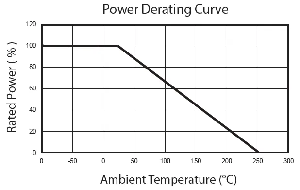
| -55°C to + 250°C |
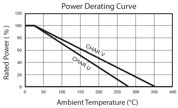
Axial | 0.1 to 15 | 500 VAC: F01, F02, F03, F04, F05, F06, F07 1000 VAC: All Others | Characteristic U: -55°C to + 275°C Characteristic V: -55°C to + 350°C |