SMPS Switch-Mode Stacked Capacitors
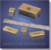
SMPS Switch-Mode Stacked ceramic capacitors feature large capacitance values and exhibit low ESR (equivalent series resistance) and low ESL (equivalent series inductance) making them well suited for high power and high frequency applications where tantalum or aluminum electrolytic capacitors may not be suitable. Johanson offers three series Stacked assemblies. The P-Series feature mechanical and pin-out configurations per DSCC 87106 and 88011 drawings while the E-Series feature mechanical and pin-out configurations more common in European design applications. The T-Series feature 200°C applications.
P-Series Capacitance Values
| Case Size | NP0 Max Capacitance (μF) | BX Max Capacitance (μF) | X7R Max Capacitance (μF) | |||||||||
|---|---|---|---|---|---|---|---|---|---|---|---|---|
| 50V | 100V | 200V | 500V | 50V | 100V | 200V | 500V | 50V | 100V | 200V | 500V | |
| P05 | 0.07 | 0.05 | 0.04 | 0.02 | 1.3 | 0.70 | 0.37 | 0.17 | 3.0 | 2.2 | 1.0 | .50 |
| P25 | 0.14 | 0.10 | 0.08 | 0.04 | 2.6 | 1.4 | 0.74 | 0.34 | 6.0 | 4.4 | 2.0 | 1.0 |
| P35 | 0.21 | 0.15 | 0.12 | 0.06 | 3.9 | 2.1 | 1.1 | 0.51 | 9 | 6.6 | 3.0 | 1.5 |
| P45 | 0.28 | 0.20 | 0.16 | 0.08 | 5.2 | 2.8 | 1.5 | 0.68 | 12 | 8.8 | 4.0 | 2.0 |
| P55 | 0.35 | 0.25 | 0.20 | 0.10 | 6.5 | 3.5 | 1.8 | 0.85 | 15 | 11 | 5.0 | 2.5 |
| P04 | 0.22 | 0.15 | 0.12 | 0.07 | 4.0 | 2.0 | 1.1 | 0.50 | 9 | 6.5 | 3.0 | 1.5 |
| P24 | 0.44 | 0.30 | 0.24 | 0.14 | 8.0 | 4.0 | 2.2 | 1.0 | 18 | 13 | 6 | 3.0 |
| P34 | 0.66 | 0.45 | 0.36 | 0.21 | 12 | 6.0 | 3.3 | 1.5 | 27 | 19 | 9 | 4.5 |
| P44 | 0.88 | 0.60 | 0.48 | 0.28 | 16 | 8 | 4.4 | 2.0 | 36 | 26 | 12 | 6.0 |
| P54 | 1.1 | 0.75 | 0.60 | 0.35 | 20 | 10 | 5.5 | 2.5 | 45 | 32 | 15 | 7.5 |
| P03 | 0.70 | 0.50 | 0.39 | 0.22 | 10 | 6.8 | 3.5 | 1.5 | 28 | 20 | 9.5 | 4.7 |
| P23 | 1.4 | 1.0 | 0.78 | 0.44 | 20 | 13 | 7.0 | 3.0 | 56 | 40 | 19 | 9.4 |
| P33 | 2.1 | 1.5 | 1.2 | 0.66 | 30 | 20 | 10 | 4.5 | 84 | 60 | 28 | 14 |
| P43 | 2.8 | 2.0 | 1.5 | 0.88 | 40 | 27 | 14 | 6.0 | 112 | 80 | 38 | 18 |
| P53 | 3.5 | 2.5 | 2.0 | 1.1 | 50 | 34 | 17 | 7.5 | 140 | 100 | 47 | 23 |
| P01 | 1.4 | 1.0 | 0.75 | 0.44 | 20 | 13 | 7 | 3.0 | 50 | 40 | 19 | 9.4 |
| P21 | 2.8 | 2.0 | 1.5 | 0.88 | 40 | 27 | 14 | 6.0 | 100 | 80 | 38 | 18 |
| P31 | 4.2 | 3.0 | 2.2 | 1.3 | 60 | 40 | 21 | 9.0 | 150 | 120 | 57 | 27 |
| P41 | 5.6 | 4.0 | 3.0 | 1.8 | 80 | 54 | 28 | 12 | 200 | 160 | 76 | 36 |
| P51 | 7.0 | 5.0 | 3.7 | 2.2 | 100 | 68 | 35 | 15 | 250 | 200 | 95 | 46 |
| P02 | 2.0 | 1.4 | 1.0 | 0.6 | 30 | 19 | 10 | 5 | 75 | 55 | 25 | 14 |
| P22 | 4.0 | 2.8 | 2.0 | 1.2 | 60 | 38 | 20 | 9 | 150 | 110 | 50 | 28 |
| P32 | 6.0 | 4.2 | 3.0 | 1.8 | 90 | 57 | 30 | 13 | 220 | 160 | 75 | 42 |
| P42 | 8.0 | 5.6 | 4.0 | 2.4 | 120 | 76 | 40 | 18 | 300 | 220 | 100 | 56 |
| P52 | 10 | 7.0 | 5.0 | 3.0 | 150 | 95 | 50 | 22 | 370 | 270 | 125 | 70 |
| P06 | 4.0 | 2.8 | 2.2 | 1.2 | 69 | 40 | 20 | 9 | 160 | 110 | 50 | 25 |
| P26 | 8 | 5.6 | 4.4 | 2.4 | 130 | 80 | 40 | 18 | 320 | 220 | 100 | 50 |
| P36 | 12 | 8.4 | 6.6 | 3.6 | 200 | 120 | 60 | 27 | 480 | 330 | 150 | 75 |
| P46 | 16 | 11 | 8.8 | 4.8 | 270 | 160 | 80 | 36 | 640 | 440 | 200 | 100 |
| P56 | 20 | 14 | 11 | 6 | 340 | 200 | 100 | 45 | 800 | 550 | 250 | 125 |
E-Series Capacitance Values
| Case Size | NP0 Max Capacitance (μF) | BX Max Capacitance (μF) | X7R Max Capacitance (μF) | |||||||||
|---|---|---|---|---|---|---|---|---|---|---|---|---|
| 50V | 100V | 200V | 500V | 50V | 100V | 200V | 500V | 50V | 100V | 200V | 500V | |
| E24 | 0.13 | 0.09 | 0.07 | 0.045 | 2.2 | 1.5 | 0.8 | 0.35 | 5.0 | 4.0 | 2.5 | 1.0 |
| E34 | 0.26 | 0.18 | 0.14 | 0.09 | 4.4 | 3.0 | 1.6 | 0.70 | 10 | 8.0 | 5.0 | 2.0 |
| E44 | 0.39 | 0.27 | 0.21 | 0.13 | 6.6 | 4.5 | 2.4 | 1.0 | 15 | 12 | 7.5 | 3.0 |
| E54 | 0.52 | 0.36 | 0.28 | 0.18 | 8.8 | 6.0 | 3.2 | 1.4 | 20 | 16 | 10 | 4.0 |
| E25 | 0.22 | 0.15 | 0.12 | 0.08 | 3.9 | 2.5 | 1.4 | 0.60 | 9.0 | 6.5 | 4.0 | 1.8 |
| E35 | 0.44 | 0.30 | 0.24 | 0.16 | 7.8 | 5.0 | 2.8 | 1.2 | 18 | 13 | 8.0 | 3.6 |
| E45 | 0.66 | 0.45 | 0.36 | 0.24 | 11 | 7.5 | 4.2 | 1.8 | 27 | 19 | 12 | 5.4 |
| E55 | 0.88 | 0.60 | 0.48 | 0.32 | 15 | 10 | 5.6 | 3.0 | 36 | 26 | 16 | 7.2 |
| E26 | 0.4 | 0.30 | 0.22 | 0.15 | 7.0 | 4.5 | 2.5 | 1.0 | 16 | 12 | 7.5 | 3.3 |
| E36 | 0.8 | 0.60 | 0.44 | 0.30 | 14 | 9.0 | 5.0 | 2.0 | 32 | 24 | 15 | 6.6 |
| E46 | 1.2 | 0.90 | 0.66 | 0.45 | 21 | 13 | 7.5 | 3.0 | 48 | 36 | 22 | 9.9 |
| E56 | 1.6 | 1.2 | 0.9 | 0.60 | 28 | 18 | 10 | 4.0 | 64 | 48 | 30 | 13 |
| E27 | 0.7 | 0.5 | 0.40 | 0.25 | 13 | 8.5 | 4.5 | 2.0 | 30 | 22 | 14 | 6.0 |
| E37 | 1.4 | 1.0 | 0.8 | 0.5 | 26 | 17 | 9.0 | 4.0 | 60 | 44 | 28 | 12 |
| E47 | 2.1 | 1.5 | 1.2 | 0.8 | 39 | 25 | 13 | 6.0 | 90 | 66 | 42 | 18 |
| E57 | 2.8 | 2.0 | 1.6 | 1.0 | 52 | 34 | 18 | 8.0 | 120 | 88 | 56 | 24 |
| E21 | 0.7 | 0.5 | 0.40 | 0.25 | 13 | 8.5 | 4.5 | 2.2 | 30 | 22 | 14 | 6.0 |
| E31 | 1.4 | 1.0 | 0.8 | 0.5 | 26 | 17 | 9.0 | 4.0 | 60 | 44 | 28 | 12 |
| E41 | 2.1 | 1.5 | 1.2 | 0.8 | 39 | 25 | 13 | 6.0 | 90 | 66 | 42 | 18 |
| E51 | 2.8 | 2.0 | 1.6 | 1.0 | 52 | 34 | 18 | 8.0 | 120 | 88 | 56 | 24 |
| E28 | 0.8 | 0.6 | 0.50 | 0.30 | 15 | 10 | 5.5 | 2.2 | 35 | 25 | 16 | 7.0 |
| E38 | 1.6 | 1.2 | 1.0 | 0.60 | 30 | 20 | 11 | 4.4 | 70 | 50 | 32 | 14 |
| E48 | 2.4 | 1.8 | 1.5 | 0.90 | 45 | 30 | 16 | 6.6 | 100 | 75 | 48 | 21 |
| E58 | 3.2 | 2.4 | 2.0 | 1.2 | 60 | 40 | 22 | 8.8 | 140 | 100 | 64 | 28 |
| E22 | 1.4 | 1.0 | 0.75 | 0.50 | 24 | 15 | 8.5 | 3.5 | 50 | 40 | 25 | 11 |
| E32 | 2.8 | 2.0 | 1.5 | 1.0 | 48 | 30 | 17 | 7.0 | 100 | 80 | 50 | 22 |
| E42 | 3.2 | 3.0 | 2.2 | 2.0 | 72 | 45 | 25 | 10 | 150 | 120 | 75 | 33 |
| E52 | 5.6 | 4.0 | 3.0 | 3.0 | 96 | 60 | 34 | 14 | 200 | 160 | 100 | 44 |
| E29 | 2.0 | 1.4 | 1.0 | 0.70 | 33 | 22 | 12 | 5.0 | 75 | 50 | 35 | 16 |
| E39 | 4.0 | 2.8 | 2.0 | 1.4 | 66 | 44 | 24 | 10 | 150 | 100 | 70 | 32 |
| E49 | 6.0 | 4.2 | 3.0 | 2.1 | 99 | 66 | 36 | 15 | 220 | 150 | 100 | 48 |
| E59 | 8.0 | 5.6 | 4.0 | 2.8 | 130 | 88 | 48 | 20 | 300 | 200 | 140 | 64 |
Mechanical Specifications
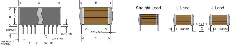
| Case Size | A | B | C | D (min) | D (max) | E | F | Leads per side |
|---|---|---|---|---|---|---|---|---|
| P05 | .120 | .185 | .250 | 0.224 | 0.275 | .300 | .080 | 3 |
| P25 | .240 | .305 | ||||||
| P35 | .360 | .425 | ||||||
| P45 | .480 | .545 | ||||||
| P55 | .650 | .715 | ||||||
| P04 | .120 | .185 | .400 | 0.350 | 0.425 | .440 | .180 | 4 |
| P24 | .240 | .305 | ||||||
| P34 | .360 | .425 | ||||||
| P44 | .480 | .545 | ||||||
| P54 | .650 | .715 | ||||||
| P03 | .120 | .185 | .450 | 0.950 | 1.075 | .500 | .180 | 10 |
| P23 | .240 | .305 | ||||||
| P33 | .360 | .425 | ||||||
| P43 | .480 | .545 | ||||||
| P53 | .650 | .715 | ||||||
| P01 | .120 | .185 | .450 | 1.850 | 2.075 | .500 | .180 | 20 |
| P21 | .240 | .305 | ||||||
| P31 | .360 | .425 | ||||||
| P41 | .480 | .545 | ||||||
| P51 | .650 | .715 | ||||||
| P02 | .120 | .185 | .800 | 1.450 | 1.535 | .870 | .530 | 15 |
| P22 | .240 | .305 | ||||||
| P32 | .360 | .425 | ||||||
| P42 | .480 | .545 | ||||||
| P52 | .650 | .715 | ||||||
| P06 | .120 | .185 | 1.250 | 1.950 | 2.075 | 1.350 | .980 | 20 |
| P26 | .240 | .305 | ||||||
| P36 | .360 | .425 | ||||||
| P46 | .480 | .545 | ||||||
| P56 | .650 | .715 |
| Size Code | A (max.) | C +/- 0.5mm (.20") | D (max.) | E (max.) | Leads per side | ||||
|---|---|---|---|---|---|---|---|---|---|
| mm | in. | mm | in. | mm | in. | mm | in. | ||
| E24 | 3.8 | 0.150 | 8.2 | 0.322 | 8.7 | 0.342 | 9.2 | 0.362 | 3 |
| E34 | 7.4 | 0.291 | |||||||
| E44 | 11.1 | 0.437 | |||||||
| E54 | 14.8 | 0.583 | |||||||
| E25 | 3.8 | 0.150 | 10.2 | 0.400 | 10.7 | 0.421 | 10.7 | 0.421 | 4 |
| E35 | 7.4 | 0.291 | |||||||
| E45 | 11.1 | 0.437 | |||||||
| E55 | 14.8 | 0.583 | |||||||
| E26 | 3.8 | 0.150 | 14.0 | 0.551 | 13.6 | 0.535 | 14.9 | 0.586 | 5 |
| E36 | 7.4 | 0.291 | |||||||
| E46 | 11.1 | 0.437 | |||||||
| E56 | 14.8 | 0.583 | |||||||
| E27 | 3.8 | 0.150 | 15.2 | 0.600 | 21.6 | 0.850 | 16.8 | 0.661 | 5 |
| E37 | 7.4 | 0.291 | |||||||
| E47 | 11.1 | 0.437 | |||||||
| E57 | 14.8 | 0.583 | |||||||
| E21 | 3.8 | 0.150 | 20.3* | 0.800* | 16.6 | 0.653 | 21.6 | 0.850 | 6 |
| E31 | 7.4 | 0.291 | |||||||
| E41 | 11.1 | 0.437 | |||||||
| E51 | 14.8 | 0.583 | |||||||
| E28 | 3.8 | 0.150 | 10.2 | 0.400 | 38.2 | 1.503 | 18.9 | 0.744 | 14 |
| E38 | 7.4 | 0.291 | |||||||
| E48 | 11.1 | 0.437 | |||||||
| E58 | 14.8 | 0.583 | |||||||
| E22 | 3.8 | 0.150 | 15.2 | 0.600 | 38.2 | 1.503 | 12.0 | 0.472 | 14 |
| E32 | 7.4 | 0.291 | |||||||
| E42 | 11.1 | 0.437 | |||||||
| E52 | 14.8 | 0.583 | |||||||
| E29 | 3.8 | 0.150 | 20.3* | 0.800* | 40.6 | 1.598 | 24.0 | 0.944 | 14 |
| E39 | 7.4 | 0.291 | |||||||
| E49 | 11.1 | 0.437 | |||||||
| E59 | 14.8 | 0.583 | |||||||
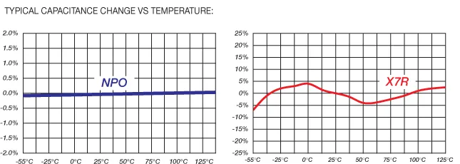
SMPS Switch-Mode Ceramic Capacitors Dielectric Characteristics
| NPO Dielectric | X7R Dielectric | |
|---|---|---|
| Temperature Coefficient: | 0 ±30ppm/°C (-55 to +125°C) | ±15% (-55 to +125°C) |
| Dissipation Factor: | 0.1% max | 2.5% max |
| Aging | None | -2.5% per decade hour |
| Insulation Resistance (Min. @ 25°C, WVDC) | 1000 ΩF or 100 GΩ, whichever is less | 500 ΩF or 50 GΩ, whichever is less |
| Dielectric Strength: | For 500V Ratings: 750VDC, 25ºC, 50mA max For 200V Ratings: 2xWVDC, 25ºC, 50mA max For 25-100V Ratings: 2.5xWVDC, 25ºC, 50mA max |
|
| Test Conditions: | 1kHz ±50Hz;1.0±0.2 VRMS | |
Features:
- E-Series Common European Lead Styles
- NPO & X7R Dielectrics, 50 to 500 VDC Ratings
- Low ESR / Low ESL, Ideal for SMPS Filtering Applications
- Custom Sizes, Voltages, and Values Available
Impedance vs Frequency:
The left-hand portion of the curves represents the capacitive reactance of two typical values. The impedance decreases until series resonance is reached. At this point (the bottom of the V), the only component of the impedance is the ESR. At higher frequencies (the inductive portion) the ESR remains relatively low so that effective filtering is maintained.
ESR vs Frequency:
These curves reflect the very low ESR of two typical values. These ESRs are much lower than Tantalums or Aluminum electrolytics of the same values. The result is the ability to provide filtering (low loss) and to handle high power requirements.
Ripple Current vs Frequency:
Here are two examples of the ability of Switch-Mode capacitors to handle high values of ripple current (high power) at various frequencies. Refer to the "AC Power Computations" applications note or contact Johanson Dielectrics Applications Engineering for more information.
Soldering Precautionstary Specifications:
The large ceramic mass of Switch-Mode capacitors increases their susceptibility to damage from thermal shock during soldering. Parts should be pre-heated to within 50°C of the peak soldering temperature and the preheating cycle's thermal gradient should be limited to a maximum of 2°C per second.
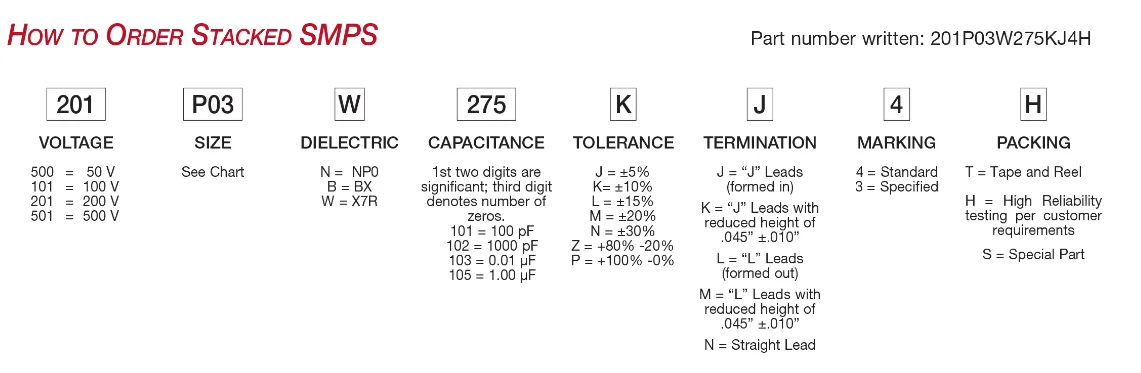
How to Order
Valid options are shown except for Capacitance
A typical PN is M2EM201B474K3J1001W. This part number breaks down as follows:
M2EM201B474K3J1001W Capacitors SMPS P-Series - 2 chips, 2324, BX, 200V, 0.47µF±10%, "J" Leads, Waffle Pack
New Johanson Global Part Number Breakdown
* Not all combinations create valid part numbers, ask our Apps Engineering Team for assistance creating a valid part number Request for assistanceClick below to see the new Global Part Number Reference Chart for this product
The legacy info below is for reference only.
Johanson has instituted a new Global Part Numbering (GPN) system.
Only the part number is changing. The parts are produced with the exact same materials, manufacturing processes, manufacturing controls, dimensions, physical attributes and testing as the parts supplied with the legacy part numbers.
The GPNs will be phased in over the next several years and are planned to be completed by January 1, 2026.
We will continue to quote and accept orders with the current (legacy) part numbers throughout this period.
Beginning January 1, 2022, all samples will be provided with the GPN.
Updates associated with this change will occur periodically.
A database for the approximate 2 million crosses can be accessed at: https://www.johansontechnology.com/pn-search