EMI FPGA SerDes Bypass
Download PDF
Simplified design and improved performance using EMI capacitors w/ Altera StratixII GX SerDes
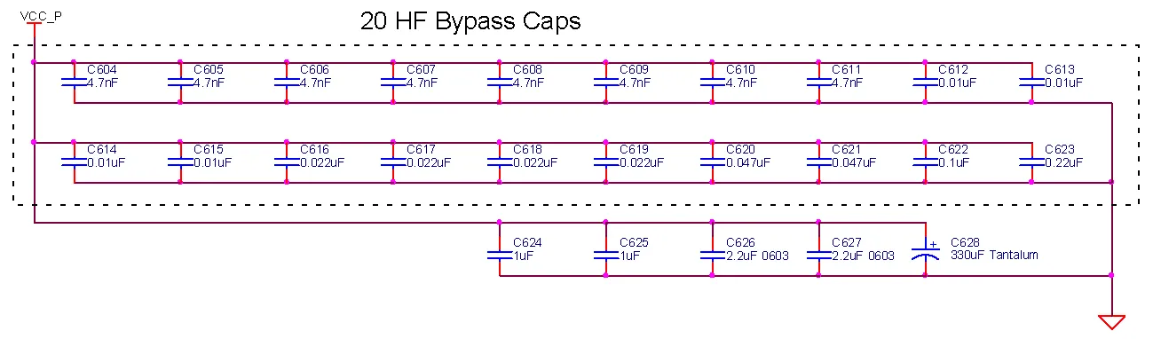
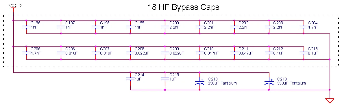
Comparative Bypass Networks
SERDES transmit power supplies:
- 13 EMI Capacitors replace 38 0402 caps
- Plane inductance saturation for each supply is achieved w/ 2 EMI capacitors
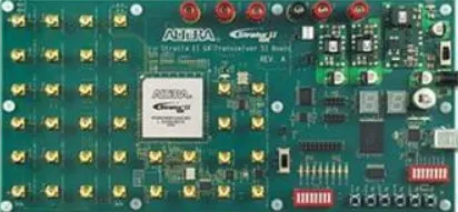
Altera® Reference Design
EMI Modified Design
EMI vs. MLCCs
MLCC Design
EMI Design
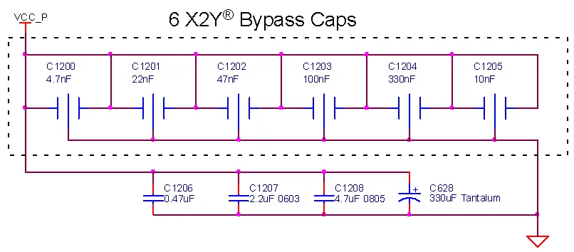
Transmit Analog: VCCH
EMI Design
- – 2 x 330uF tantalum caps
- + 2 MLCCs + 7 EMI
- – 1D < 80mOhms
- equivalent resistive to 250MHz
- Ignores spatial effects and IC parasitics
- Spatial effects dominate above 10MHz
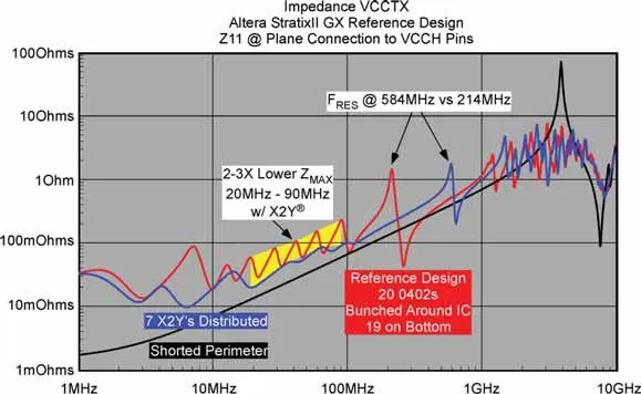
Impedance Comparisons w/o IC
2-3X lower impedance 20MHz-100MHz w/ 7 caps instead of 20
- >2.5:1 Higher FRES
- 2.5:1 reduction in Q
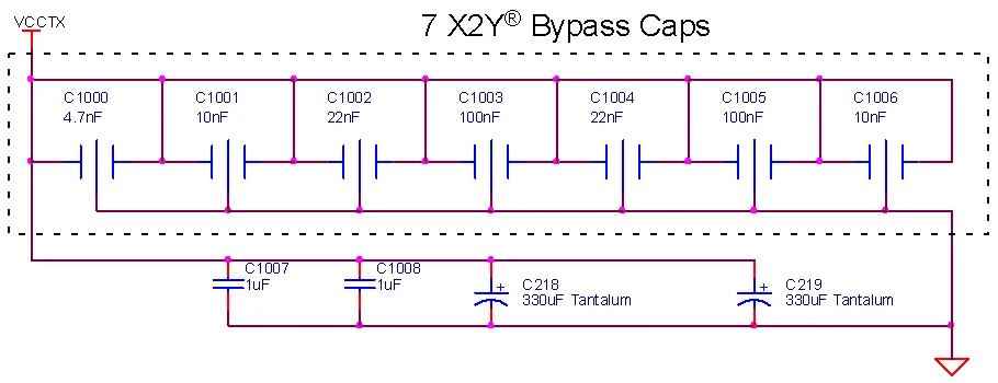
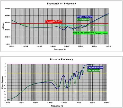
Original VCCTX and EMI Networks

Original Network, FDTIM
- LBYPASS decreases with increasing freq.
- Near 20MHz about LTOTAL about 220pH
- Die / bypass PRF near 200MHz
- Bypass / PCB PRF near
EMI network selective zeroes
- Lower LBYPASS @ 20MHz up
- Zero for Die / bypass PRF
- Zero for PCB / bypass PRF
VCCTX PCB / Bypass Resonance
Original network
- @ relatively low PRF
EMI Network
- Lower distributed L of 6/7 EMI caps raises to 580MHz
- Suppressed w/ single 100pF rated EMI
- Good suppression w/ conventional caps difficult due to high Q
- Measured results, PRF completely suppressed
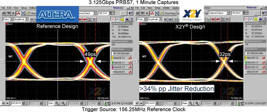
3.125Gbps Performance PRBS7
EMI Redues jitter to 32ps p-p jitter
- vs 49ps in reference design
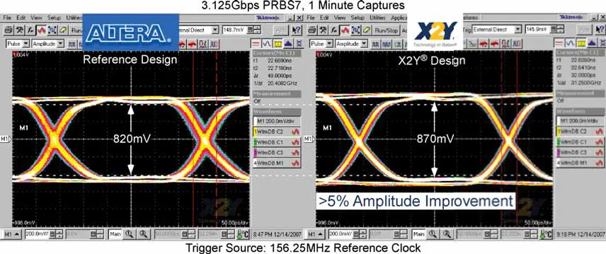
EMI improves better eye amplitude >5%
- 870mV pp @ sample point vs 820mV pp reference
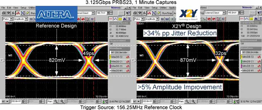
3.125Gbps Performance PRBS23
Shows same improvements in jitter and eye amplitude:
- EMI 32ps p-p jitter vs 49ps in reference design
- EMI 870mV pp vs 820mV pp in reference design