Polyterm® Flexible SMD Termination
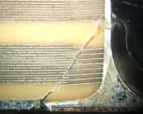
Cracked capacitors can manifest themselves as latent defects including increased leakage current, intermittent opens, shorts or no problem found when field returned assemblies are analyzed. In some cases these defects can lead to catastrophic failure depending on the application energy available. Cracks could be introduced at virtually any point in the surface mount assembly process from pick and place, soldering and reflow, handling after assembly, de-paneling, and board level testing or equipment assembly (see below example of standard termination after flexing). Board flexure and handling are the predominant source of capacitor cracking. Polyterm® flexible SMD termination was developed to provide a flexible bond capable of withstanding higher physical strain than standard terminations. Standard terminations are more susceptible to cracking during processing, which may not be discovered by visual means. Over time these cracks can propagate into opposing electrodes within the capacitor possibly causing the capacitor to fail short and subsequent catastrophic failure. Polyterm®, in addition to proper board layout practices, provides added protection and greatly reduces the possibility of the capacitor failing due to these board stresses.
Performance verification of the Polyterm® flexible SMD termination was performed on the R15 (0805), R18 (1206), S41 (1210), S43 (1812), R29 (1808), S47 (2220), X43 (1812) and X44 (1410) size capacitors. These tests were conducted based on industry standards. JIS-C-6429, IEC-384-1, IEC 60068-2-21.
Testing Procedure
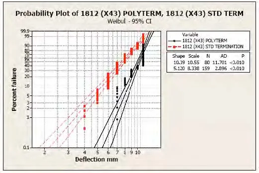
Group 1) 80 samples and were subjected to gradual bending measured incrementally in 1 mm steps from 1mm to 10mm. A failure would be indicated by loss of capacitance >10% (JIS-C-6429) and >5% for X43 and X44 X2Y capacitors. These samples were then removed from the board and the terminations were etched from the capacitor body. The ceramic body was then physically inspected for damage. Both Polyterm® and Standard terminations were subjected to this experiment. Each different part size is represented by the summary of test results (Figure 1) and a graph showing cumulative failure of both Polymer and standard terminations (Figures 2-9)
Group 2) Samples were bent to varying degrees of deflection to provide photographic representation of how the polymer terminations perform and illustrate how failures manifest themselves. This test was performed using the S47 (2220) sample group (figures 10-14). One board for each mm of deflection was used.
| X7R Dielectric | Mean Bend (mm) Standard Termination | Mear Bend (mm) Polyterm® | Component Flex improvement with Polyterm® |
|---|---|---|---|
| R15 0805 | 3.4 | 9.8 | +188% |
| R18 1206 | 3.3 | 9.1 | +175% |
| S41 1210 | 4.2 | 9.6 | +128% |
| S43 1812 | 3.9 | 8.9 | +128% |
| R29 1808 | 3.0 | 6.2 | +106% |
| S47 2220 | 3.8 | 6.7 | +75% |
| X44 1410 | 5.5 | 9.6 | +75% |
| X43 1812 | 7.2 | 9.4 | +30% |
Note 1: All temperature refer to topside of the package, measured on the package body surface.
Figure 1
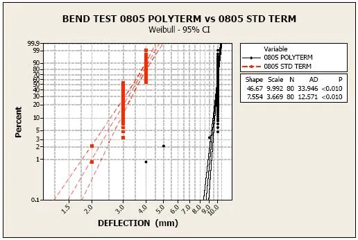
Figure 2
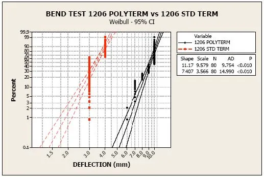
Figure 3
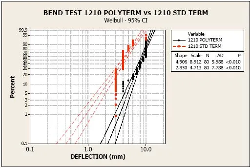
Figure 4
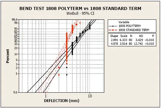
Figure 5
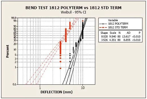
Figure 6
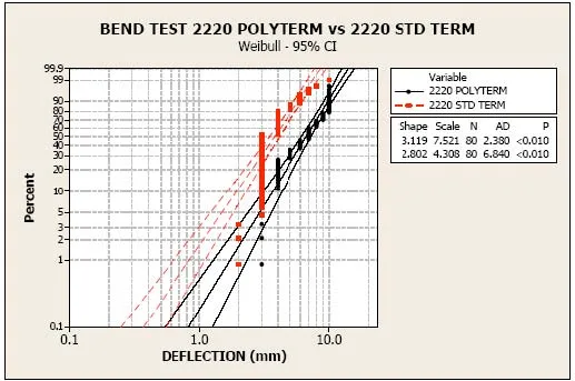
Figure 7
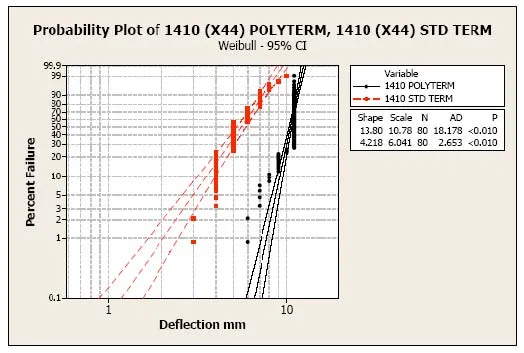
Figure 8
POLYTERM® CROSS SECTION ANALYSIS
Undamaged termination
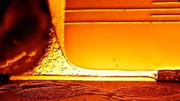
Figure 10 Undamaged termination 1mm deflection
At 3mm only partial separation of the polymer was visible. The silver layer is clearly separating from the polymer with no ceramic damage visible.
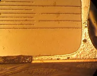
Figure 11 Partial separation of polymer 3mm deflection
The photo in Figure 12 shows almost complete separation of the silver termination from the polymer layer. Although the polymer layer is partially separated the capacitor still operates normally. When returned to the original state all capacitors regardless of failure operated within specification.
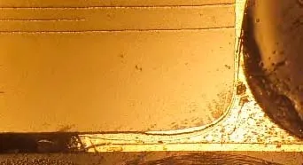
Figure 12 Partial Separation of Polymer 4mm
Complete separation of the polymer layer may cause open capacitor, but ceramic failure was not observed. This will protect against the capacitor failing short causing catastrophic failure.
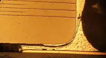
Figure 13 Complete Separation of Polymer Layer 5mm
Capacitor with complete separation of Polyterm® termination

Figure 14 Capacitor with complete separation of Polyterm® termination during flex testing.
TEST BOARD AND FLEX TESTING EQUIPMENT
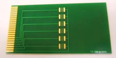
Figure 15 Flex Test Board
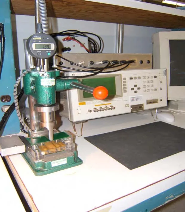
Figure 16 Flex Test Fixture W/CPU for Data Storage
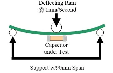
Figure 17 illustration of bend test
Conclusion
Polyterm® flexible SMD termination is useful in reducing or eliminating MLCC failures due to PCB flexure stresses related to PCB assembly operations and/or harsh operating environments. Although all components may exhibit some termination separation there was no degradation observed that would interfere with the capacitors operation or performance. Polyterm® in addition to proper board layout and handling can greatly reduce or eliminate failures associated with MLCC cracking.
Notice: Specifications are subject to change without notice. Contact your nearest Johanson Dielectrics, Inc. Sales Office for the latest specifications. All statements, information and data given herein are believed to be accurate and reliable, but are presented without guarantee, warranty, or responsibility of any kind, expressed or implied. Statements or suggestions concerning possible use of our products are made without representation or warranty that any such use is free of patent infringement and are not recommendations to infringe any patents. The user should not assume that all safety measures are indicated or that other measures may not be required. Specifications are typical and may not apply to all applications.