Soldering and Handling Precautions for Large Form Capacitors and Planar Arrays
General
Ceramic capacitors having body sizes larger than 1812 and planar arrays are known to be very susceptible to thermal shock damage due to their large ceramic mass. Soldering temperature profiles used must provide adequate temperature rise time and cool-down time to prevent damage due to thermal shock. The potential for thermal shock cracking is related to the mass of the capacitors, not to any manufacturing defect. These large parts require more care during installation than the smaller more common surface mount devices.
These guidelines are emphasized because cracking or other damage caused by handling or thermal shock is not necessarily apparent under ordinary visual inspection techniques. The damage can be very small (micro-cracks) and can occur under the terminations where even high magnification cannot detect them. The problem is further complicated by the fact that these micro-cracks may not be initially detectable by standard electrical testing. Once initiated, the cracks can grow with time and cause latent failures. Attention to these details will aid in the successful use of the inherently reliable multilayer ceramic capacitor.
Component Handling
Damage to large capacitors can also be caused by improper handling. Johanson Dielectrics takes great care during the manufacturing processes to make sure that such damage does not occur. At the user's facility, it is equally important that careful handling be observed from receiving to stock to kitting and throughout the assembly and test.
For very large surface mount chips and especially the stacked Switch-Mode capacitors, additional precautions are necessary. From chip to final testing, the devices are kept separate from one another to prevent chipping and cracking. The packaging for shipment is in foam cushioned pockets especially designed for this purpose. The shipping containers should be utilized as much as possible to make sure that the capacitors cannot bump against each other. If ESD packages are used in kitting or storage, make sure that the capacitors are cushioned inside these packages. If a large capacitor is accidentally dropped on a hard surface, it should not be used even if it appears intact.
Soldering Attachment Process
PREHEAT is a critical step of any soldering process. the circuit assembly should be preheated as shown in the recommended profiles to within 65 to 100°C of the maximum soldering temperature. Johanson Dielectrics recommends that thermal gradients (of any heating or cooling process) not exceed 2°C per second. Temperature change should be distributed as evenly as possible throughout the capacitor body as applying heat or cold to a localized spot on the device may result in thermal gradients great enough to cause cracking.
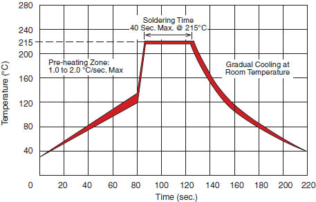
REFLOW SOLDERING is accomplished by several common methods including infra-red, convection and radiant heating. Recommended temperature profile limits for these are shown in Figure (1).
VAPOR PHASE REFLOW produces consistent circuit heating with reflow occurring at a temperature determined by the boiling point of the liquid used, typically 215°C. Recommended temperature profile limits for vapor phase reflow are shown in Figure (2).
WAVE SOLDERING can be utilized, but the preheat requirements generally make this process very difficult to accomplish. Wave soldering is not recommended for the Switch-Mode or larger H-Series capacitors due to the incompatibility of the chip's mass with the steep temperature gradient typically present in this process.
HAND SOLDERING is discouraged due to its process control limitations. In the event that hand soldering must be used the following precautions should be observed. The iron should be a low wattage type (30 watt max). The circuit and device must be pre-heated to 150°C at a rate ≤ 2°C/sec. The soldering iron tip must be placed on the circuit board pad, not on the device body or leadframe.
Very large components such as stacked Switch-Mode devices may need to be preheated separately. One possible method is to preheat the capacitors in a convection oven, remove one at a time (use insulated tongs or similar to retain heat evenly), place on preheated board and solder using flux-core wire solder and a soldering iron just large enough to reflow the solder. This operation must take place quickly so that the capacitor does not have a chance to cool down more than 100°C below the peak soldering temperature.
An alternate method of keeping the capacitors at the preheat temperature is to remove them from the oven and place them under an IR lamp until ready to solder.
COOL DOWN After the solder reflows properly the assembly should be allowed to cool gradually, again maintaining the thermal gradient of 2°C/sec. maximum at room ambient conditions. Attempts to speed this cooling process or immediate exposure of the circuit to cold cleaning solutions increase the possibility of thermal shock cracking of the ceramic capacitor.
FIG. 1: SOLDER REFLOW TEMPERATURE LIMITS
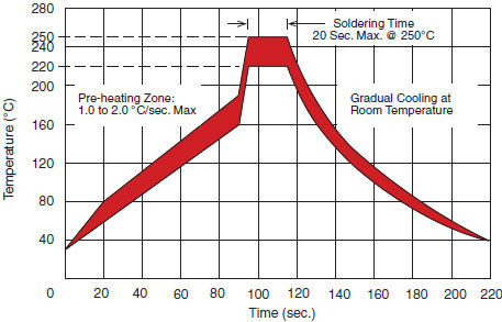
FIG. 2: VAPOR PHASE REFLOW TEMPERATURE LIMITS